I am currently developing the RTno which helps to develop an embed and RT-middleware available device.
RTno is a library and a bridging software to develop an RTC available device using arduino.
1. What is RT middleware?
RT middleware is a platform software for robots and robotic system in which robotic element devices are distributedly controlled and assembling system is realized by conjunctioning those software ‘components’.

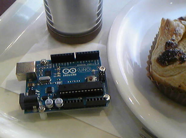
2. What is arduino?
arduino is an embedded prototyping MCU board. The arduino is opensource software and hardware!
If you want more information, access arduino.cc
")
3. What is RTno?
RTno is a platform software which is appropriate for developing an RT-middleware available embedded device using arduino.
Let’s see figure below. RTno is a framework which is constructed of an arduino’s library (RTno) and bridging software (RTnoProxy). You can use a template source code. Just modify the template, then you can get a lot of advantages of RTno!

In developing embedded devices which are used with the PCs, developers must make both microcontroller’s software and PC-side software (APIs). These are RED components in the figure below.
Though users can use the APIs (YELLOW part) which encapsulate the communication protocols between PCs and devices, system integrators must read a lot of thick documents of APIs.
For researchers usually, they must make both APIs and user programs.

The device developers (manufacturers) use RT-middleware, which make it much easier for users to develop their own programs. RT-middleware provides common and intuitive interfaces.
However, the manufacturers must develop APIs and RTCs!!

However, RTno framework reduce (often delete) the RTC development, so device developers can focus on the arduino programming. RTno framework encapsulates the communication between arduino and PC (GREEN).
The bridging software (RTnoProxy) collects RTC available interface information from arduino, then it automatically changes its own interfaces. This is why the arduino can communicate with the other RTCs using simple interfaces (you can use integer, or float values. you do not have to create your own protocols. You do not need to think about byte alignment, and those complicated problems…)

Moreover, if you are developing your own device and software, you can create the embedded device which directly communicate with the other RTCs (of course this communication is virtually accomplishment by using the RTnoProxy;-) You do not need to be worried about the complicated communication problems. This may be the fastest proto-typing way!!!

arduino uses 8 bit MCU, AVR, so the RTno and RT-middleware might be too rich, but this toolbox is surely suitable for the begineers both of embedded device programming and RT-middleware.
If you already know about the RT-middleware, you can use simple and easy arduino prototyping for your hacks! RTno provides the same code when you program your own RTCs.
If you are an arduino user, RTno provides very simple and rich communication tool. This will introduce you into the RT-middleware world!!
RTno (arduino Library)
GITHUB: https://github.com/ysuga/RTno
RTnoProxy (Bridging software)
GITHUB: https://github.com/ysuga/RTnoProxy
Installer (Win):
OpenRTM-aist 1.1.0 RTnoProxySetup_v016.zip
Former version:
Installer (Win):
RTnoProxySetup015.zip
RTnoProxySetup014.zip
RTnoProxySetup013.zip
RTnoProxySetup011
1. Setup arduino
From arduino official site, download arduino_XXXX and extract the zip file. You do not have to any installing process. Just use arduino.exe. I usually place the extracted arduino folder directly on the C drive.
2. Setup OpenRTM-aist
From OpenRTM-aist official size, download OpenRTM-aist C++ Release version.

3. Setup RTno
Download RTno from https://github.com/ysuga/RTno.
If you want to get zip archive, see below:

When you extract the zip file, you will get ysuga-RTno-XXXX folder. RENAME the folder to “RTno”.
In “RTno” folder,
- example ・・・ RTno example
- RTno.h ・・・ RTno main header.
- RTno.cpp ・・・ RTno main routine
- The other sources
Some archive software automatically create an intermediate folder, but these files must be directly in the RTno folder.
Place the RTno folder in the arduino’s libraries folder. For me, in “C:\arduino_XXXX\libraries\”.

When launching arduino IDE, you can see [sketch]>>[import libraries]>>[RTno]

Confirming installation
5. RTno Proxy
In windows you can install the RTnoProxy using MSI installer.
You can also get the newest RTnoProxy code.
https://github.com/ysuga/RTnoProxy
Build it VC2008 (Windows) or just make in Linux.
% unzip src.zip
% cd RTnoProxy20101115
% make
After build/make, in RTnoProxy/bin folder
- DataPortTestComp: For Test
- RTnoProxy.conf: Configuration File
- RTnoProxyComp: RTnoProxy
- rtc.conf: Basic Configuration File for RT component (RTC)
1. Writing program into arduino microcontroller board
Let’s check RTno using digitalInOut.pde in the example folder.
Open digitalInOut.pde from arduino IDE.

Usually we modify the code, but now let us use it.
If you want to implement your own code from scratch, use RTnoTemplate.pde.
Now let us start to write the software to MCU.
First, check the COM number of the arduino using device manager or something. Then change the arduino setting from tool menu.


Then, click upload button, then compilation is started and the IDE will upload the program to arduino microcontroller board.

When the uploading is done, the board is automatically reset. After reset, the arduino is waiting for the request from RTnoProxy launched in the PC.
2. Setting of RTnoProxy
At first, Serial Port setting.
In the installed folder (maybe C:\Program Files\ysuga_net\RTnoProxy) or, bin folder (if you compile it manually), you can find “RTnoProxy.conf”.
In default,
  #conf.default.comport:\\\\.\\COM4
  conf.baudrate: 19200
  conf.default.comport:/dev/ttyACM2
#is comment. In windows, uncomment the first line and comment out the last line. Then modify the COM number.
(\\\\.\\ is important. It’s escape strings. If you use COM9 or higher COM port, the escape strings is necessary.)
You can modify the communication rate (boardrate). This value, of course, must be equal to the value which is selected in RTno device side. This feature is useful if you use XBee and on-the-fly writing.
*IMPORTANT*
Windows 7 and Vista has UAC (user access control). It prevents your modification.
Solution1) Just stop UAC.
Solution2) Copy the setting file on your desktop, and delete the original file. After the modification, copy to the original location.
3. Launch RTnoProxy
RTnoProxy is an RT component. So first, start Name Service. In windows, you can launch NameService from [Start]>>[Programs]>>[OpenRTM-aist]>>[C++]>>[tools]>>[Start Naming Service].
In Linux, just type “rtm-naming”. But in Linux, usually the default portnumber is already used by CORBA naming service, so use 9999 or other port number. Type “rtm-naming 9999”.

Then, setting of RTnoProxyComp.
In the installed folder or bin folder, you can find rtc.conf.
In the rtc.conf file……
corba.nameservers:127.0.0.1:2809
exec_cxt.periodic.rate:100.0
Test.RTnoProxy.config_file: RTnoProxy.conf
logger.enable:NO
The important points are the first line, and second line. They are the nameserver setting and execution rate (unit is Hz) respectively. Linux users had better modify the port number. This modification might also be prevented by the UAC in Windows 7 or Vista.
That’s all. Launch RTnoProxyComp. You will find the console output like “Opening SerialPort(COM*)…OK.”, and after 3 seconds, onInitialize is called. In the onInitialize function, RTnoProxy and arduino negotiate each other. In DigitalInOut, L type (TimedLongSeq) InPort named “in0”, and OutPort “out0” are added.

If you restart the RTnoProxy, you must reset the arduino. In Windows, the automatic reset is NOT executed so you must reset it manually by pressing the reset button on the arduino board (or disconnect and connect).
4. Test
Launch RT System Editor. In Windows, [Start]>>[Programs]>>[OpenRTM-aist]>>[C++]>>[tools]>>[RT System Editor].
In Linux, please refer the official website. It’s provided as an Eclipse plugin.

This is RT System Editor.

First, add the nameserver. (In usual cases, the default nameserver (localhost:2809) is automatically added if the server is already launched.). Press the button shown in the following figure:

Then, set the IP address and port number of your name service.

Then, you can find your name service.

If RTnoProxy is launched, the name service view is like ….

Then, launch DataPortTestComp.

Use RT System Editor to connect them. In the RT System Editor, select [File]>>[Open New System Editor], or click [Online System Editor] button.

Drag and drop the DataPortTest0 and RTnoProxy0. You will find the DataPorts are added correctly.

Connect the DataPorts. The DigitalInOut has InPort and OutPort (both are TimedLongSeq type.), so connect the same type ports of DataPortTest.

Check the flow type. It should be “push”.

Connect the input-output, and output-input ;-)

Then, activate all components. If they are activated successfully, their colors turn to green.

If you check your arduino board, RX and TX LEDs are repeatedly flashing. This is why the arduino and PC are communicating.
Check the console of DataPortTestComp. 6 dataset of LongSeq type are received. They are arduino’s pin-input (2-7). If you connect switches or some digital sensors, you will find the corresponding data is changed.

On usual arduino board, LED is connected to 13th pin. Let’s try to flash it.
Select the console window of DataPortTestComp, then press shift and ‘L’ key (upper case.). This is sometimes fails if you keep pressing the key. Just press one time.

Then, set the number of element of the output dataset. Input ‘6’ and press enter key.

Then, input data in 6 times.
Now let’s output {1, 1, 1, 1, 1, 1}. You will input
1[Enter]1[Enter]1[Enter]1[Enter]1[Enter]1[Enter]

If you finish inputting the last (6th) data, the dataset is sent to arduino, and LED is turned on. If you send zero, the LED is turned off.
digitalInOut Source Code
Digital Input/Output
/** * digitalInOut.pde * RTno is RT-middleware and arduino. * * Using RTno, arduino device can communicate any RT-components * through the RTno-proxy component which is launched in PC. * Connect arduino with USB, and program with RTno library. * You do not have to define any protocols to establish communication * between arduino and PC. * * Using RTno, you must not define the function "setup" and "loop". * Those functions are automatically defined in the RTno libarary. * You, developers, must define following functions: * int onInitialize(void); * int onActivated(void); * int onDeactivated(void); * int onExecute(void); * int onError(void); * int onReset(void); * These functions are spontaneously called by the RTno-proxy * RT-component which is launched in the PC. */ #include /** * This function is called at first. * conf._default.baudrate: baudrate of serial communication * exec_cxt.periodic.type: reserved but not used. */ void rtcconf(void) { conf._default.baudrate = 19200; exec_cxt.periodic.type = ProxySynchronousExecutionContext; } /** * Declaration Division: * * DataPort and Data Buffer should be placed here. * * Currently, following 6 types are available. * TimedLong: * TimedDouble: * TimedFloat: * TimedLongSeq: * TimedDoubleSeq: * TimedFloatSeq: * * Please refer following comments. If you need to use some ports, * uncomment the line you want to declare. **/ TimedLongSeq in0; InPort in0In("in0", in0); TimedLongSeq out0; OutPort out0Out("out0", out0); ////////////////////////////////////////// // on_initialize // // This function is called in the initialization // sequence. The sequence is triggered by the // PC. When the RTnoRTC is launched in the PC, // then, this function is remotely called // through the USB cable. // In on_initialize, usually DataPorts are added. // ////////////////////////////////////////// int RTno::onInitialize() { /* Data Ports are added in this section. */ addInPort(in0In); addOutPort(out0Out); // Some initialization (like port direction setting) for(int i = 0;i < 6;i++) { pinMode(2+i, INPUT); } for(int i = 0;i < 6;i++) { pinMode(8+i, OUTPUT); } return RTC_OK; } //////////////////////////////////////////// // on_activated // This function is called when the RTnoRTC // is activated. When the activation, the RTnoRTC // sends message to call this function remotely. // If this function is failed (return value // is RTC_ERROR), RTno will enter ERROR condition. //////////////////////////////////////////// int RTno::onActivated() { // Write here initialization code. return RTC_OK; } ///////////////////////////////////////////// // on_deactivated // This function is called when the RTnoRTC // is deactivated. ///////////////////////////////////////////// int RTno::onDeactivated() { // Write here finalization code. return RTC_OK; } ////////////////////////////////////////////// // This function is repeatedly called when the // RTno is in the ACTIVE condition. // If this function is failed (return value is // RTC_ERROR), RTno immediately enter into the // ERROR condition.r ////////////////////////////////////////////// int RTno::onExecute() { /* * Input digital data */ if(in0In.isNew()) { in0In.read(); for(int i = 0;i < in0.data.length() && i < 6;i++) { digitalWrite(8+i, in0.data[i]); } } /* * Output digital data in Voltage unit. */ out0.data.length(6); for(int i = 0;i < 6;i++) { out0.data[i] = digitalRead(2+i); } out0Out.write(); return RTC_OK; } ////////////////////////////////////// // on_error // This function is repeatedly called when // the RTno is in the ERROR condition. // The ERROR condition can be recovered, // when the RTno is reset. /////////////////////////////////////// int RTno::onError() { return RTC_OK; } //////////////////////////////////////// // This function is called when // the RTno is reset. If on_reset is // succeeded, the RTno will enter into // the INACTIVE condition. If failed // (return value is RTC_ERROR), RTno // will stay in ERROR condition.ec /////////////////////////////////////// int RTno::onReset() { return RTC_OK; } |
First, the communication setting is defined.
/** * This function is called at first. * conf._default.baudrate: baudrate of serial communication * exec_cxt.periodic.type: reserved but not used. */ void rtcconf(void) { conf._default.baudrate = 19200; exec_cxt.periodic.type = ProxySynchronousExecutionContext; } |
In default, the baudrate is 19200. The exec_cxt.periodic.type defines type of periodic execution, but currently not in use.
Next, InPort and OutPort, and the data buffers are defined.
TimedLongSeq in0; InPort in0In("in0", in0); TimedLongSeq out0; OutPort out0Out("out0", out0); |
Then, in onInitialize, the ports are added. Pin output/input is also set. pin 2-7 are input, and 8-13 are output.
addInPort(in0In); addOutPort(out0Out); // Some initialization (like port direction setting) for(int i = 0;i < 6;i++) { pinMode(2+i, INPUT); } for(int i = 0;i < 6;i++) { pinMode(8+i, OUTPUT); } |
Nothing is done in onActivated and onDeactivated. But you can also execute some initialization codes here.
In onExecute, you can describe the periodic routine.
int RTno::onExecute() { /* * Input digital data */ if(in0In.isNew()) { in0In.read(); for(int i = 0;i < in0.data.length() && i < 6;i++) { digitalWrite(8+i, in0.data[i]); } } /* * Output digital data in Voltage unit. */ out0.data.length(6); for(int i = 0;i < 6;i++) { out0.data[i] = digitalRead(2+i); } out0Out.write(); return RTC_OK; } |
Here, if the arduino receives data with in0In port, the received data is output to digital output pins. The status of digital Input pins is sent to the out0Out port.
At first, build your circuit board with bread board.
Materials you must prepare are ….
- Arduino UNO
- Bread Board
- LED
- Resister 470 ohm
- Switch
- Jamp wires
They may be included in some kit for arduino beginners.

The longer leg of your LED is usually ‘+’ side (Anode).
Register must be form by bending its legs.

Put your LED and register as shown in the following figure.

One side of the register is connected to LED’s longer leg (Anode).
Another side of the register is connected to 5V.

The other side of the LED (shorter leg) and arduino No.8 pin are connected.

Put your switch on the bread board.

One side of the switch is GND pin, another side is No.2 pin of arduino.

Following diagram shows the connection of the circuit.

Programming
Launch ‘arduino’ developmental environment.
You must install RTno library first.
Press ‘Open’ then open the ‘RTnoTemplate’.


Save and name other name. Here, I named it ‘myDigitalInOut’.

Then, edit the file.
#include void rtcconf(void) { conf._default.baudrate = 57600; exec_cxt.periodic.type = ProxySynchronousExecutionContext; } TimedLongSeq in0; // 入力データの入る変数 InPort in0In("in0", in0); // 入力ポートの宣言.onInitializeで追加しないとだめ TimedLongSeq out0; // 出力データを入れるための変数 OutPort out0Out("out0", out0); // 出力ポート.これも追加処理が必要 int RTno::onInitialize() { /* Data Ports are added in this section. */ addInPort(in0In); // 入力ポートの追加 addOutPort(out0Out); // 出力ポートの追加 // Some initialization (like port direction setting) for(int i = 0;i < 6;i++) { pinMode(2+i, INPUT); // 2~7ピンを入力ピンに設定 digitalWrite(2+i, HIGH); // ここで内部プルアップをONに } for(int i = 0;i < 6;i++) { pinMode(8+i, OUTPUT); // 8~13番ピンを出力に設定 } return RTC_OK; } int RTno::onExecute() { /* Input digital data */ if(in0In.isNew()) { // データが来ていたらIf文に入る in0In.read(); // ここでようやく読み込む for(int i = 0;i < in0.data.length() && i < 6;i++) { // length関数でシーケンス配列の長さが分かるので digitalWrite(8+i, in0.data[i]); // 配列形式でアクセスできます } } /* Output digital data in Voltage unit. */ out0.data.length(6); // length関数に引数を与えるとシーケンス配列の長さを設定できる for(int i = 0;i < 6;i++) { out0.data[i] = digitalRead(2+i); // 配列にデータを代入して } out0Out.write(); // ここでデータを出力ポートから排出 return RTC_OK; } |
Let’s test!
Write to board
Select your arduino. “Tools”>>”Board”>>”Arduino UNO”, if you use Arduino UNO.

Select your COM port. You can find the information in Device Manager.
href=”http://ysuga.net/wp-content/uploads/2011/03/image121.jpg”>
Upload the program. Press Upload Button.

OK if Done Uploading is displayed.

Test
1. Launch NameServer
2. Configure RTnoProxy.conf
############# RTnoProxy.conf ########### conf.default.comport:\\\\.\\COM10 conf.default.baudrate:57600 #conf.default.comport:/dev/ttyACM0 #################################### |
3. Launch RTnoProxy
4. Launch DataPortTestComp
5. Launch RT System Editor.
6. Open ‘New Online System Editor’ in RT System Editor. Clicking the button below is also ok.

7. Drag&Drop RTnoProxy0.rtc and DataPortTest0.rtc from NameService View to System Editor.
8. Connect TimedLongSeq type ports

9. Activate all
10. Select DataPortTest’s console, and input ‘L (greater case)’ then press enter key. This make the dataPortTest RTC to DataSending Mode.
11. Input length of the array 6.
12. Then input the sending data, and enter key (this is repeated 6 times.)
13.If the last 6th data is input, the data array is sent from the output port.
14.LED is on if data is “0 0 0 0 0 0”. LED if off if “1 1 1 1 1 1”.
15. Input ‘v’ in the DataPortTest console and press enter. You can find the data sent to the input port.
16. Compare input data if switch is pressed (or not).